
 |
Final Design | April 17th, 2010 |
|
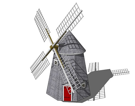
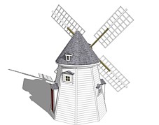
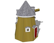
In addition to being an outgrowth of the many mills that were measured
and researched for this project, the Yorktown Windmill design went through
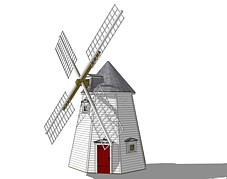
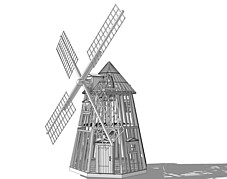
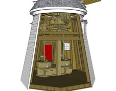
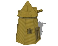
several iterations before it found it's final form. The drawings shown
here show several of the design stages that the project went through.
As you can see from the drawings, the original mill was somewhat taller and
had a shaller cap than the final design. The design allowed more of the
brake wheel to be housed in the second floor. | |||
|  
| ||
|
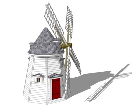
As the windmill design transformed from being a fixed system to being
a mobile design, it was necessary to reduce the scale to make it manageable
by a team of assemblers. The second floor was compressed to be a simple
machine housing and the main shaft was reduced accordingly. Because the gear
system had already been constructed, it was necessary to adapt the new design
to accomodate the existing components. Consequently, the cap is a bold 54
degrees - allowing the 8 foot brake wheel to fit snugly into it.
To view an animation of how the unit is assembled, click here. | |||
|  
| ||
| 
| 
| |
|
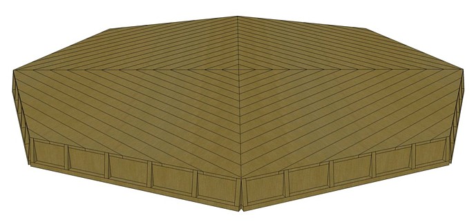
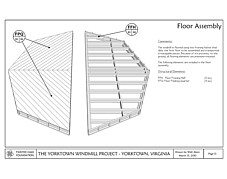
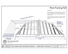
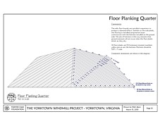
Not terribly exotic, the foundation of the windmill is remarkably stout.
It is constructed from pressure treated lumber and features doubled 2x6
floor joists that provide exceptional support with a minimum of depth.
The general design allows the floor to be split into halves that are
used to bind four of the first floor wall panels to create a portal
unit.
Because shrinkage is always a concern with pressure treated lumber, each of
the floor boards has a batten installed beneath that will prevent weather
exposure when the boards shrink as they dry. | |||
| |||
| 
| 
| |
|
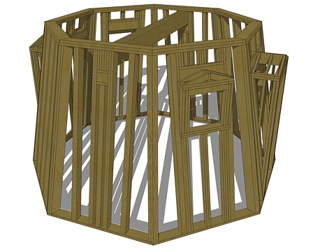
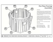
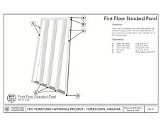
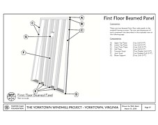
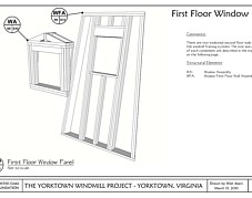
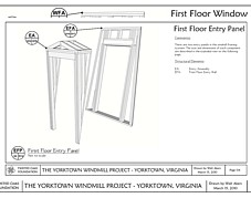
The first level contains the pediment, the stone cases and the hoppers. A large
center brace supports the gear system that resides in the second level -
providing expansive space for the miller and hios customers. Notably, all of
the walls of the windmill are canted at 11 degrees to allow for the rotation
of the sails. | |||
|  
| ||
| 
| 
| |
|
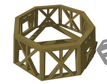
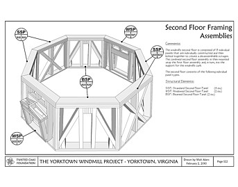
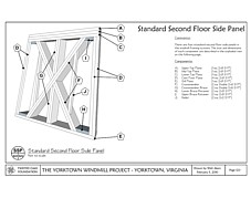
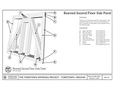
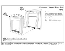
Also called the second level, the machine housing is where the Wallower,
the Great Spur Wheel and the Stone Nuts reside. It is a foreshortened
structure that allows the maximum amount of wooden gears in the minimum
space. | |||
  | |||
| 
| 
| |
|
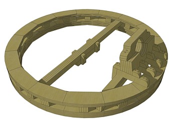
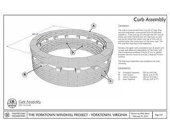
Unlike a 'Live Curb' which has cast iron wheels on which the cap
rotates, a dead curb is simply a pair of greased wooden plate. Rather than
using animal lard, the Yorktown Windmill's dead curb has several layers of
shallac that are topped off with a coat of paste wax. Remarkably, because of the
scale of the mill and the precision of the curb's fit, once the initial
friction bond is broken the cap can be turned easily by one man. | |||
| |||
|
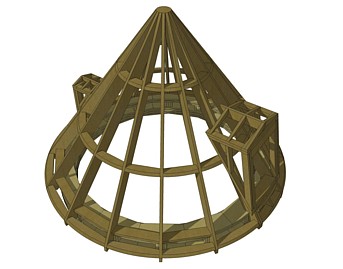
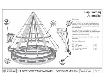
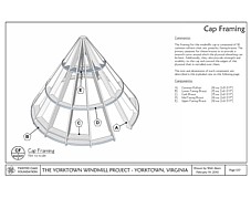
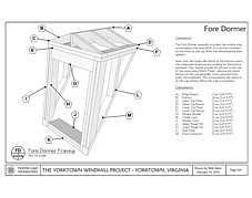
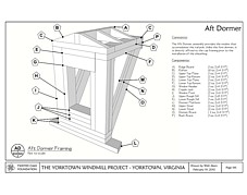
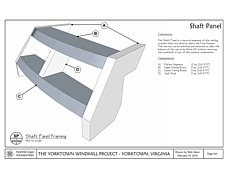
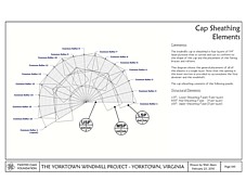
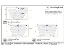
The windmill's cap is a model of simplicity and elegance. With only 16 rafters
and a variety of fairing braces, the cap is more remeniscent of a ship's ribs
than a building roof. The rafters are covered with 1/4" birch plywood that is
pre-cut to the proper size and then bent to fit. 3 Layers deep, the plywwod
sheathing has wood glue between each layer and is topped with 15# construction
paper and Blue Label cedar shingles - the finest available. | |||
| |||
| 
| 
| |
| 
| 
| |
|
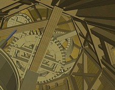
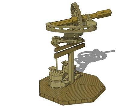
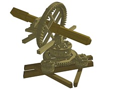
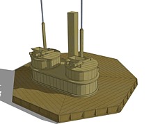
Finally, the building would be for nought were it not for the system of gears
that transfer power from the sails to the millstones. The diagrams here show
how the gears are installed within the mill. | |||
|  
| ||
